 English
  日本語
日本語  한국어
한국어  Deutsch
  Español
  italiano
  русский
  português
  العربية
  ไทย
ไทย  tiếng việt
  中文
中文


NEWS

BKN eddy current testing machines provide non-destructive inspection for tubes, bars, and wires, detecting surface defects, cracks, and material inconsistencies while supporting high-speed production, automation, customization, and reliable industrial quality control.
An ultrasonic flaw detector sends short, high-frequency sound pulses into a test material through a transducer. When the sound reaches a boundary or discontinuity, part of its energy is reflected. The transducer receives these returning echoes, and the instrument analyzes their travel time and amplitude. With suitable calibration and a defined inspection procedure, these signals help inspectors locate and evaluate possible internal discontinuities without cutting or damaging the component.
An ultrasonic flaw detector typically uses several components to generate, transmit, receive and interpret ultrasonic signals:
Pulser and receiver: The pulser produces a short electrical pulse, while the receiver amplifies and processes the returning signal.
Transducer: The transducer converts electrical energy into ultrasonic waves and converts returning sound energy back into electrical signals.
Couplant: In contact testing, couplant helps transfer ultrasonic energy between the transducer and the test surface by reducing the air gap.
Display and signal-processing system: The instrument displays the returning echoes and provides information such as signal amplitude and travel time.
Calibration reference: A suitable reference block or known reflector is used to establish the inspection range, sensitivity and evaluation conditions.
The inspection process follows a signal path from pulse generation to echo evaluation:
Electrical pulse generation: The instrument sends a short electrical pulse to the transducer.
Ultrasonic wave generation: The transducer converts the electrical pulse into mechanical vibrations and introduces ultrasonic waves into the test material.
Wave propagation: The sound waves travel through the material. Their behavior depends on the material, geometry, probe frequency and inspection angle.
Reflection from boundaries or discontinuities: When the sound reaches a back wall, material interface or discontinuity, part of the sound energy is reflected.
Echo reception: The transducer receives the returning sound and converts it into an electrical signal.
Signal display and evaluation: The flaw detector displays the echoes. Inspectors compare their position, amplitude and pattern with the calibrated reference and applicable inspection procedure.
This pulse-echo process allows internal conditions to be evaluated from the returning signals rather than by cutting open the component.
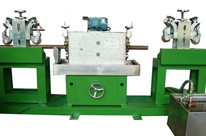
Ultrasonic flaw detectors commonly evaluate three main signal characteristics:
Time of flight: The time between pulse transmission and echo reception helps estimate the reflector’s position when the sound velocity of the material is known.
Echo amplitude: Signal amplitude indicates the strength of the reflected sound but is also affected by probe position, reflector orientation, surface condition and calibration.
Echo pattern: The number, position and movement of echoes can help distinguish the back wall, geometric features and possible discontinuities.
An echo does not automatically confirm a defect. The result must be evaluated using the correct calibration, scanning technique, acceptance criteria and inspection standard.
For a more detailed explanation of reflected-wave evaluation, read the ultrasonic flaw detector theory page.
| Factor | Effect on the inspection |
|---|---|
| Material and grain structure | Coarse or non-uniform structures may scatter or attenuate sound waves. |
| Component geometry | Curved surfaces, edges and complex shapes may create additional reflections. |
| Surface condition and coupling | Rough surfaces or inconsistent coupling may reduce signal transmission. |
| Probe frequency and angle | Probe selection affects penetration, resolution and sensitivity to differently oriented discontinuities. |
| Discontinuity orientation | A discontinuity may produce a weak echo if its orientation does not reflect sufficient sound toward the transducer. |
| Calibration and procedure | Inspection range, sensitivity and evaluation depend on correct calibration and defined acceptance criteria. |
These factors should be considered together. Changing the probe, scanning direction or inspection setup may change the received signal even when the tested component remains the same.
Ultrasonic flaw detection can be used to inspect welds, steel bars, pipes, forgings, castings and other suitable industrial components. The appropriate setup depends on the material, component dimensions, expected discontinuity type, required inspection coverage and applicable standard.
However, ultrasonic testing also has practical limitations. Complex geometry, coarse-grained materials, rough surfaces, poor coupling and unfavorable discontinuity orientation can make signals more difficult to interpret. Reliable inspection therefore requires suitable equipment, calibrated references, a defined procedure and trained personnel.
Selection should begin with the inspection task rather than the instrument alone. Important information includes:
Test material and component dimensions
Expected defect type, location and orientation
Required inspection area and production speed
Surface condition and available access
Applicable testing and acceptance standards
Manual, semi-automatic or automatic inspection requirements
BKN provides ultrasonic testing equipment for industrial inspection applications. Share your material, dimensions, inspection target and applicable standard through the contact page to discuss a suitable ultrasonic testing solution.


